Finite Element Analysis (FEA) and Computer-Aided Design (CAD) are cornerstone technologies in modern engineering, enabling the design, simulation, and optimization of complex systems and components. FEA simulates physical behavior to predict how designs will perform under real-world conditions, while CAD facilitates precise modeling of those designs. Together, they streamline product development across industries like automotive, aerospace, and manufacturing. This 800-word overview explores the principles, applications, benefits, challenges, and future trends of FEA and CAD integration.
Principles of FEA and CAD
FEA and CAD work in tandem to create and validate engineering designs:
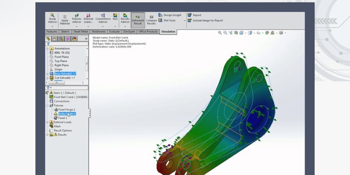
CAD Modeling: CAD software, such as SolidWorks, AutoCAD, or CATIA, allows engineers to create detailed 2D and 3D models of components or systems. These models define geometry, materials, and boundary conditions for further analysis.
Finite Element Analysis: FEA divides complex geometries into smaller, manageable elements (meshes) to simulate physical phenomena like stress, deformation, or heat transfer. Software like ANSYS, Abaqus, or COMSOL solves mathematical equations to predict system behavior.
Mesh Generation: FEA relies on meshing, where CAD models are discretized into finite elements. The mesh quality and density impact simulation accuracy and computational efficiency.
Boundary Conditions and Loads: Engineers apply real-world conditions, such as forces, pressures, or temperatures, to CAD models within FEA software to simulate operational scenarios.
Simulation and Analysis: FEA software solves equations for each element, analyzing responses like stress distribution, vibration, or thermal performance, enabling engineers to identify potential failure points.
Iterative Optimization: CAD and FEA enable iterative design refinement, where engineers modify models based on simulation results to improve performance, safety, and efficiency.
Applications of FEA and CAD
FEA and CAD are integral to a wide range of industries:
Automotive: CAD designs vehicle components like chassis and engines, while FEA simulates crashworthiness, structural integrity, and thermal management, ensuring safety and performance.
Aerospace: FEA analyzes aircraft wings, fuselages, and turbine blades for stress, fatigue, and aerodynamics, while CAD creates precise models to meet stringent regulatory standards like DO-160.
Civil Engineering: CAD models bridges, buildings, and dams, and FEA evaluates their stability under loads like wind, earthquakes, or traffic, ensuring structural safety.
Consumer Products: CAD designs ergonomic products like smartphones or appliances, while FEA tests durability, drop resistance, and thermal performance for reliability.
Manufacturing: FEA optimizes tooling and machinery designs, reducing material waste and wear, while CAD ensures precise fabrication and assembly processes.
Medical Devices: CAD models prosthetics or implants, and FEA simulates biomechanical interactions to ensure compatibility and durability in the human body.
Benefits of FEA and CAD Integration
The integration of FEA and CAD offers significant advantages:
Reduced Prototyping Costs: Virtual simulations in FEA reduce the need for physical prototypes, saving up to 30% in development costs, according to industry studies.
Improved Design Accuracy: FEA identifies stress concentrations, deformations, or thermal issues early, enabling CAD modifications to enhance design reliability and performance.
Faster Time-to-Market: Iterative simulations streamline the design process, allowing engineers to test multiple scenarios virtually, accelerating development cycles.
Enhanced Safety: FEA ensures designs meet safety standards by simulating extreme conditions, reducing risks in applications like automotive crash testing or aerospace components.
Material Optimization: FEA analyzes material performance, enabling engineers to select lightweight, cost-effective materials in CAD, reducing production costs and environmental impact.
Cross-Disciplinary Collaboration: CAD and FEA provide a common platform for mechanical, structural, and thermal engineers, fostering collaboration and reducing design errors.
Challenges in FEA and CAD
Despite their benefits, FEA and CAD integration presents challenges:
Computational Demands: High-fidelity FEA simulations require significant computational resources, especially for complex models with fine meshes, increasing processing time and hardware costs.
Model Accuracy: Inaccurate CAD geometries or oversimplified FEA assumptions can lead to unreliable results, requiring expertise to balance accuracy and computational efficiency.
Learning Curve: Mastering CAD and FEA software demands training in modeling, meshing, and simulation techniques, which can be time-consuming for new users.
Software Costs: Licenses for advanced CAD and FEA tools, such as ANSYS or SolidWorks, are expensive, posing a barrier for small organizations or startups.
Interoperability Issues: Compatibility between CAD and FEA platforms can be limited, requiring data conversion or additional software to ensure seamless integration.
Future Trends
The future of FEA and CAD is shaped by technological advancements and industry needs:
Cloud-Based Simulation: Cloud platforms like ANSYS Discovery or Autodesk Fusion 360 enable remote CAD modeling and FEA simulations, reducing hardware costs and supporting global collaboration.
AI and Machine Learning: AI optimizes mesh generation, predicts failure modes, and automates design iterations, enhancing FEA accuracy and reducing computation time.
Generative Design: CAD tools with generative design algorithms create optimized geometries based on FEA constraints, enabling lightweight, efficient designs for aerospace and automotive applications.
Digital Twins: FEA and CAD are integral to digital twins, providing real-time virtual models for monitoring and optimizing physical systems throughout their lifecycle.
Sustainability Focus: FEA and CAD are supporting eco-friendly designs by optimizing material use and simulating energy-efficient systems, aligning with global sustainability goals.
Conclusion
FEA and CAD are indispensable tools in modern engineering, enabling precise design and robust analysis of complex systems. Their integration streamlines development, reduces costs, and enhances reliability across industries like automotive, aerospace, and medical devices. While challenges like computational demands and software costs persist, advancements in AI, cloud computing, and generative design are expanding their capabilities. As industries demand innovative, sustainable solutions, FEA and CAD will continue to drive progress, shaping the future of engineering design and performance optimi