Finite Element Analysis (FEA) and Computer-Aided Design (CAD) are pivotal technologies that have transformed the engineering landscape, enabling precise design and robust analysis of complex systems. FEA simulates the physical behavior of structures under various conditions, while CAD provides the digital framework for creating detailed 3D models. Together, they enhance efficiency, reduce costs, and foster innovation across industries like aerospace, automotive, and manufacturing. This article explores their fundamentals, integration, applications, benefits, challenges, and future trends in engineering.
What Are FEA and CAD?
Computer-Aided Design (CAD) is a software-based tool that allows engineers to create, modify, and optimize 2D or 3D models of physical objects. Popular CAD platforms, such as AutoCAD, SolidWorks, and CATIA, enable detailed design visualization and iterative refinements, serving as the foundation for product development. These models act as digital blueprints, facilitating collaboration and manufacturing.
Finite Element Analysis (FEA) is a numerical method that divides a complex structure into smaller elements to analyze its response to forces, heat, vibration, or other physical effects. By solving mathematical equations, FEA predicts stress, deformation, and potential failure points. Software like ANSYS, Abaqus, and COMSOL Multiphysics are widely used for these simulations.
Integration of FEA and CAD
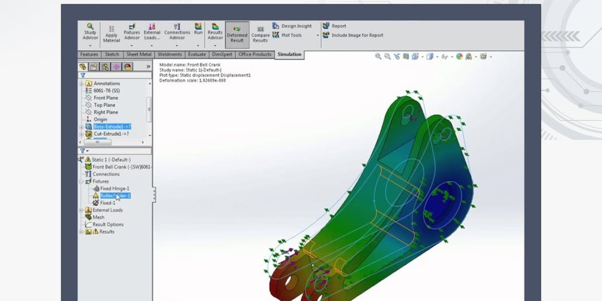
The synergy between FEA and CAD streamlines the engineering process. CAD models provide the geometry that FEA analyzes, with seamless data transfer via integrated tools or plugins (e.g., SolidWorks Simulation). This integration offers:
Design Validation: Testing CAD models for structural integrity without physical prototypes.
Iterative Refinement: Adjusting designs based on FEA insights to optimize performance.
Efficient Workflow: Automating transitions between design and analysis phases.
For example, designing a bridge involves creating a CAD model, then using FEA to assess load distribution and material stress, ensuring safety and durability.
Key Components
CAD Features: Include sketching, parametric modeling, assembly design, and rendering capabilities.
FEA Process: Encompasses meshing, applying boundary conditions, solving equations, and interpreting results.
Integration Tools: Software interfaces that link CAD and FEA for a cohesive workflow.
Hardware Requirements: High-performance computing systems to handle complex simulations.
Benefits of FEA and CAD
The combination delivers significant advantages:
Cost Reduction: Minimizes prototype development costs by validating designs virtually.
Time Savings: Accelerates design cycles with rapid iterations and simulations.
Enhanced Accuracy: FEA provides detailed stress and strain data, improving reliability.
Innovation Enablement: Supports testing of novel materials and geometries.
Safety Assurance: Identifies weaknesses early, enhancing product safety.
Applications Across Industries
FEA and CAD are essential in diverse fields:
Automotive: Designs chassis, engines, and safety systems, with FEA testing crashworthiness.
Aerospace: Optimizes aircraft wings, turbines, and fuselages for weight and strength.
Manufacturing: Creates precise molds and machinery, validated by FEA.
Civil Engineering: Analyzes structures like bridges and skyscrapers for load capacity.
Medical Devices: Designs implants and prosthetics, ensuring biocompatibility.
Challenges in FEA and CAD
Despite their benefits, challenges persist:
Technical Complexity: Requires specialized skills to master both tools.
Computational Demand: High-fidelity FEA needs powerful hardware, increasing costs.
Model Accuracy: Errors in CAD geometry or meshing can skew FEA results.
Software Compatibility: Integrating different platforms can be problematic.
Data Interpretation: Analyzing FEA outputs demands expertise to avoid misjudgments.
Future Trends
The future of FEA and CAD is driven by innovation:
Artificial Intelligence (AI): AI optimizes designs by predicting outcomes and suggesting enhancements.
Cloud Computing: Facilitates remote access and collaborative simulations.
Additive Manufacturing: Supports 3D printing with CAD and FEA for complex parts.
Digital Twins: Enables real-time FEA on virtual replicas for ongoing monitoring.
Automation: Automates meshing and analysis, reducing manual effort.
The push for Industry 4.0 and sustainable design further accelerates their adoption, supporting eco-conscious engineering.
Career Opportunities
Professionals skilled in FEA and CAD are in demand, with roles like CAD designer, FEA analyst, and simulation engineer. Opportunities span design firms, manufacturing, and research sectors. Certifications in tools like SolidWorks or ANSYS boost employability, offering competitive salaries and career advancement as of July 25, 2025.
Conclusion
FEA and CAD together redefine engineering by enabling precise design and thorough analysis. They cut costs, save time, and drive innovation across industries. Despite challenges, advancements like AI and cloud computing enhance their potential. As technology evolves, these tools will remain crucial, empowering engineers to create safer, more efficient, and sustainable solutions.